Calculate ACI 318-19 Table 6.6.3.1.1(b) effective moment of inertia for columns, walls, beams & slabs. Get Ieff instantly. Try the free template now.

This template is not available yet. You can sign up and create it yourself!
Or let us know if you'd like to be notified when it’s ready:
No items found.
No items found.
About this ACI 318 Effective Moment of Inertia Calculator
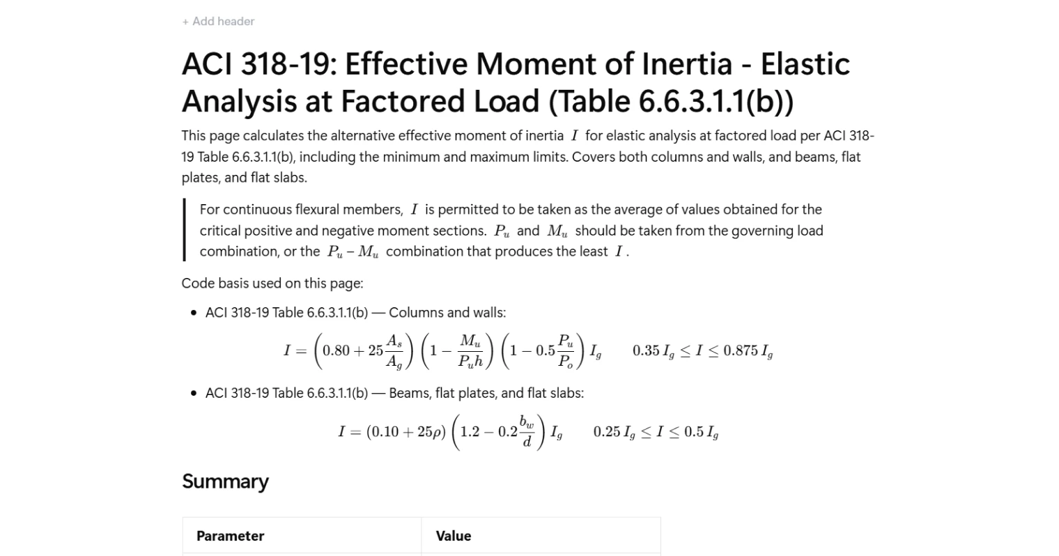
This calculator determines the effective moment of inertia for reinforced concrete members according to ACI 318 Table 6.6.3.1.1(b). It evaluates the alternative stiffness formulation used for elastic analysis under factored loads and applies the code-specified minimum and maximum limits. The calculator supports both compression members (columns and walls) and flexural members (beams, flat plates, and flat slabs).
- Structural engineer — quickly evaluate the effective stiffness of reinforced concrete members for frame analysis models or design checks.
- Design engineer — verify the governing effective moment of inertia used in structural analysis against ACI provisions.
- Engineering consultant — document how stiffness reductions are calculated and ensure traceable alignment with ACI code requirements.
This is an engineering-grade calculator built for CalcTree. It exposes the intermediate terms and governing limits so engineers can audit how the final effective moment of inertia is determined.
More info on ACI 318 Effective Moment of Inertia
Member classification
The calculator distinguishes between two member categories defined in ACI 318: compression members (columns and walls) and flexural members (beams, flat plates, and flat slabs). Each category uses a different expression from Table 6.6.3.1.1(b). A selection input determines which formulation governs the calculation.
Input parameters
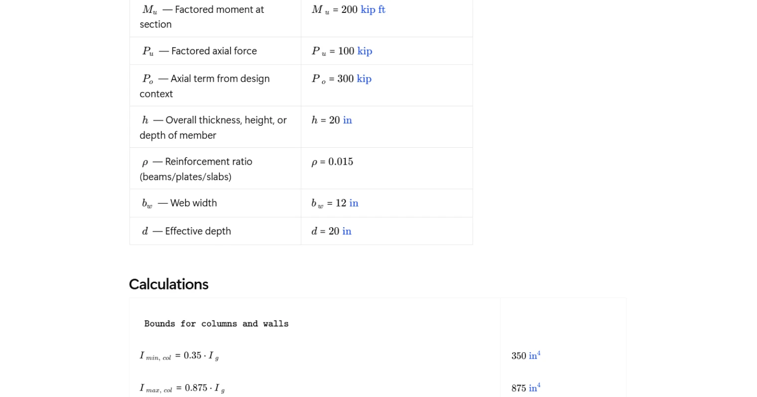
The calculation requires section properties, reinforcement information, and design load effects. For compression members, the formulation uses the ratio of reinforcement area to gross section area, the factored moment relative to axial load and member depth, and an axial load reduction term related to nominal axial capacity. For flexural members, the formulation depends on the reinforcement ratio and the ratio between web width and effective depth.
These inputs allow the calculation to capture how reinforcement content, geometry, and load effects influence the effective stiffness used in structural analysis.
Effective moment of inertia calculation
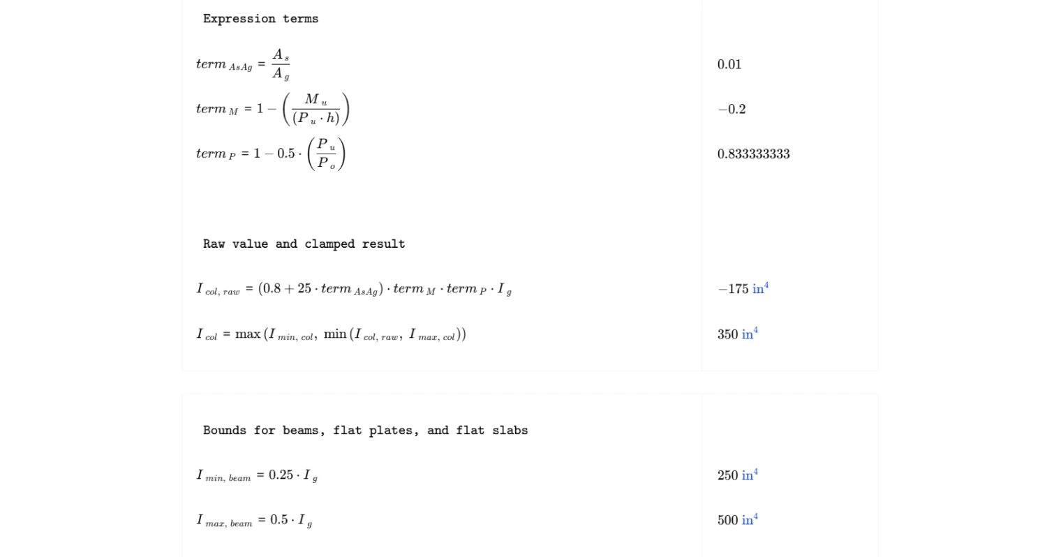
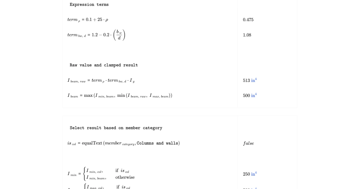
For columns and walls, the expression modifies the gross moment of inertia using three factors: reinforcement ratio, moment–axial interaction, and axial load level. The resulting value is then limited within the code-specified bounds.
For beams, flat plates, and flat slabs, the effective inertia is determined using a reinforcement ratio term and a geometric modification factor based on the web width to effective depth ratio. This result is also constrained by minimum and maximum limits specified by ACI.
Governing result and bounds
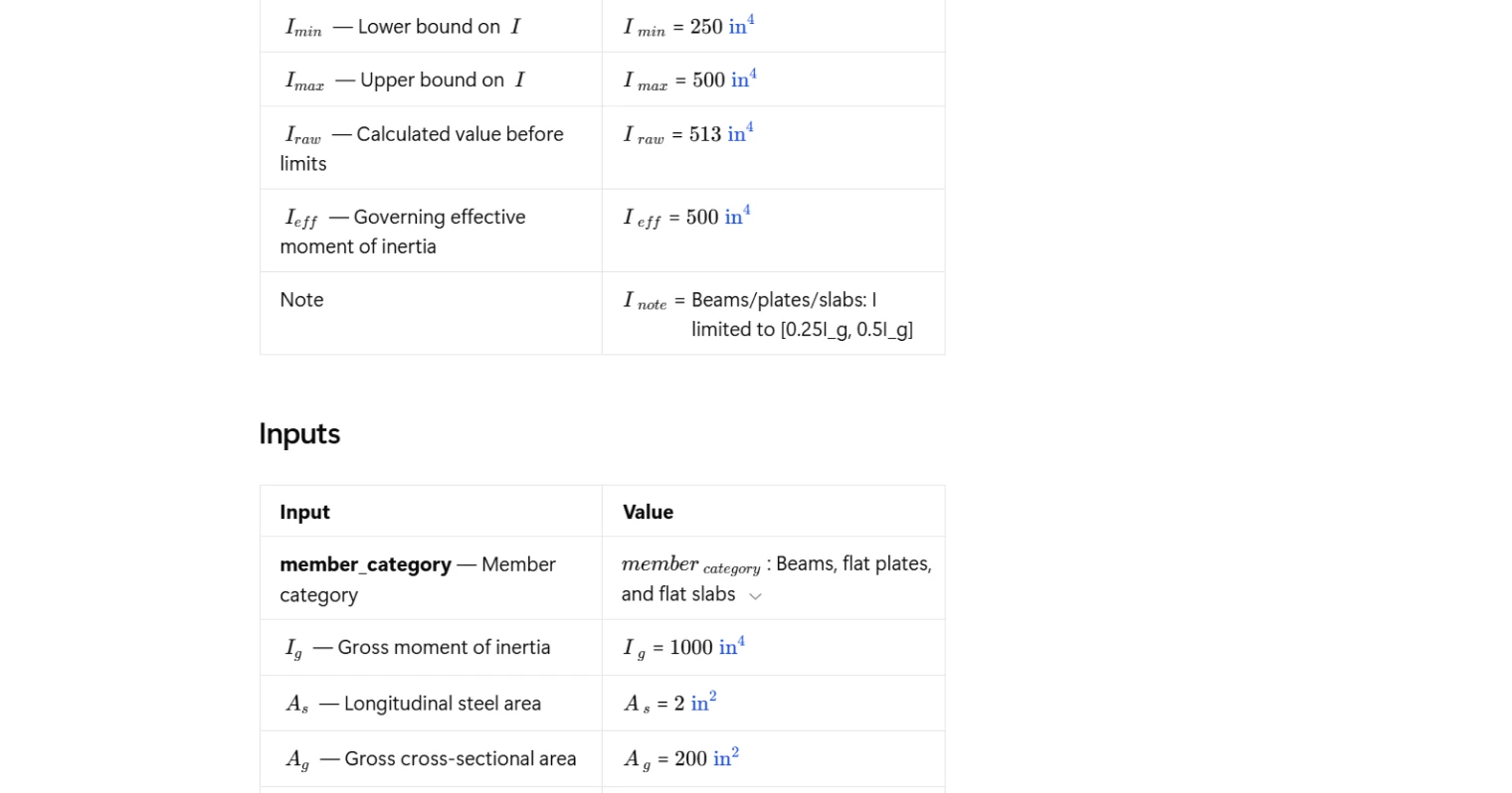
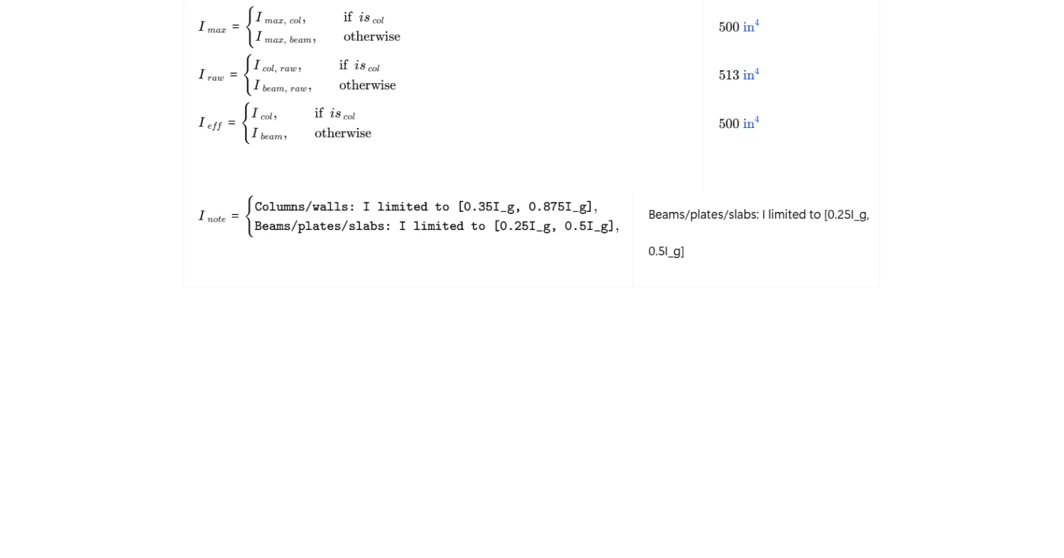
After calculating the raw effective inertia, the result is clamped between the minimum and maximum values required by the code. The calculator reports the lower bound, upper bound, calculated raw value, and the final governing effective moment of inertia used for analysis.
A note is also generated to indicate which set of ACI limits governs the result based on the selected member category.
Common Calculation Errors to Avoid
- Using inconsistent load combinations — the axial force and bending moment should come from the governing factored load combination or the combination that produces the least effective stiffness.
- Incorrect reinforcement ratio definition — ensure reinforcement ratios are calculated using the correct steel area and gross section area for the member.
- Ignoring code limits on effective inertia — the raw calculated value must always be limited within the minimum and maximum bounds specified by ACI.
- Mixing member categories — the equations for compression members differ from those for flexural members, so selecting the correct member type is critical.
- Using inconsistent section dimensions — geometric parameters such as web width, effective depth, and overall depth must correspond to the same section used to compute the gross moment of inertia.
Engineering templates
Common calculators
Design guides
FAQs
What is the effective moment of inertia and why does ACI 318-19 require it?
Concrete members crack under load, which reduces their stiffness below the gross section value. Using the full gross moment of inertia Ig in elastic analysis would overestimate stiffness and underestimate deflections and lateral drift. ACI 318-19 Table 6.6.3.1.1(b) provides empirical expressions that account for cracking and reinforcement content, giving a more realistic I for use in first-order and second-order elastic analysis under factored loads.
Why are there separate formulas for columns/walls versus beams, flat plates, and flat slabs?
The two member categories behave differently under load. Columns and walls carry significant axial force, which suppresses cracking and increases effective stiffness. Their formula includes Pu, Mu, and the reinforcement ratio As/Ag to capture this interaction. Beams, flat plates, and flat slabs carry predominantly flexure with little to no axial load, so their simpler formula depends on the longitudinal reinforcement ratio rho and the web geometry ratio bw/d.
What Pu–Mu combination should I use as input for a column or wall?
ACI 318-19 requires using the Pu–Mu combination that produces the least I, which typically means the combination with the highest moment-to-axial ratio. You should check all governing load combinations and select the one that gives the lowest calculated I before limits are applied. This is the conservative approach and ensures the stiffness used in analysis is not overstated.
How does the calculator handle the minimum and maximum limits on I?
The raw value Iraw is calculated directly from the ACI expression without limits. The code then clamps this result between the prescribed bounds: 0.35Ig to 0.875Ig for columns and walls, and 0.25Ig to 0.5Ig for beams, flat plates, and flat slabs. The summary table shows Iraw alongside Imin, Imax, and the final governing Ieff so you can see whether the limits controlled.
How do I handle continuous flexural members such as beams continuous over supports?
For continuous members, ACI 318-19 permits taking I as the average of the effective values calculated at the critical positive and negative moment sections. Run the calculation separately for each critical section using the corresponding Mu and reinforcement layout, then average the results before applying them in your structural model.
Can this calculation be used for second-order P-delta analysis?
Yes. ACI 318-19 Table 6.6.3.1.1(b) is explicitly intended for elastic analysis at factored load, which includes second-order analysis. The effective I from this table captures the cracked stiffness needed to correctly assess lateral drift amplification and moment magnification in sway frames or slender columns.
Learn about the benefits of using CalcTree on engineering projects!